Monday, April 25, 2016

ProtoScrewShield Kit Retail

Proto Screw Shield, Arduino in a bag in a frustratingly words that conjure up images of a prototype of drilling (I had to look it up), (who is not there?). That is not quite what we're going for, but you're imagining a versatile prototyping shield, that just about any electronic component, you're definitely on the right track with a CAN interface. Proto Screw Shield is always useful with screw terminal combines our proven Arduino ProtoShield.


In this guide, we hope to put together a fully-functional, Proto Screw Shield'll try to get. Assembly section, just a little something to push you in the direction of your next project will be followed by instructions to use.
ProtoScrewShield Kit Retail
Proto Screw Shield assembling
You've probably noticed that the product looks nothing like the picture you've got pretty packaging. Before prototyping, screwing, and ... err ... talisman can begin, you need to assemble the Proto Screw Shield. Assembly is pretty straightforward, but it's easy to be through-hole soldering. If this is your first time picking up a soldering iron, I first would like to encourage you to attack one of our excellent tutorial on soldering. We are looking for someone to screw the shield is more like a piece of modern art, an enjoyable Arduino shield (yeah, that's only for the purpose of punishment is linked to The Simpsons clip) than do not want to end.

ProtoScrewShield Kit Retail
At least, a couple of tools required for assembly of opposable, is really a basic soldering iron, solder a bit, and some are cutting. In addition to the equipment, and other items to help you keep everything nice and stable, needle nose pliers, and possibly a third hand, or can be included in the vise.
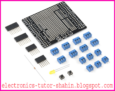
Before starting assembly, empty out your bag and make sure you've got all the parts should be:
  • PCB screw 1x Shield
  • 1x 5mm yellow LED
  • 1x 330Ω resistor
  • 2x 6-pin Stackable Headers
  • 2x 8-pin Stackable Headers
  • Momentary push button 2x
  • 6x 2-pin 3.5mm screw terminals
  • 8x 3-pin 3.5mm screw terminals
If any part is missing? (Bad SparkFun kitters!) Drop an email to our customer service team. We'll leave them to you as soon as possible.

Now, dig and find yourself familiar with the PCB screw Shield. If you're like me, you probably have to flip it back over and a couple of dozen times to figure out which side is the top. To avoid assembling the shield upside-down, remember that all parts of the outline with the top side of the PCB. It looks like this:

ProtoScrewShield Kit Retail
At the top of the element that you need to insert the PCB, and soldering leads downwards.
ProtoScrewShield Kit Retail
MSPAINT skills beyond compare...
If it was not obvious enough already, where each component of the plan will ultimately Proto Screw Shield itself as a good way to be exhibiting. I work from the lowest profile element, meaning starting with 330Ω resistor, buttons, LED (polarity must be careful!), And finally followed by paretabe header'd say. This method ensures that the material is generally flush with the PCB as possible, as are seated. You look pretty enough to take home to mother Proto Screw Shield, do not want?
A special note on the header, two in fact. Board labels are not nearly as clear as they should; You can insert just the header, where they go on the diagram to ensure that yesterday. Some places look like they can be inserted in the header, and if they do not go into these remote locations, will not be compatible with your shield Arduino-. Secondly, when you welded headers, as straight as possible to take care of them. I am the first of each solder pin, and then plug it into my Arduino all six or eight, the header pins are soldered to make sure everything lines up before, like.

Now, all that remains of the screw terminals. If you have not noticed how much the screw terminal rule, I invite you to take a closer look. Have you noticed how they slide together to form mega-screw-terminal? 2, 4, 6, and 8 varieties (of the three) of the formation of mega-screw-terminal combination of 2- and 3-pin screw terminal use. Necessary in order to complete all the mega-screw-terminal screw terminal there is enough, and should be filling your Proto Screw Shield. Screw terminals to ensure that the slide Take care of each other equally.

Mega-in screw-terminal complete with all of them in their respective PCB footprints in the insert. Verify that all of the input screw terminal is facing toward the outside of the PCB. Suppose you flip the board in each of the screw terminals and solder them into place as well. You may need an extra bit of solder to the pins. Proto Screw Shield looks something like the picture below you, then congratulations! If it is not, well, maybe you should invest in some solder wick; This is a bad time to learn how to solder!

ProtoScrewShield Kit Retail
How to use Proto Screw Shield
Proto Screw Shield's prototyping area looks simple enough to use, but it may be dangerous for the health of your circuit if you plan to take part in it without soldering. Screw Shield is a lot of behind the scenes much more complicated than it looks and prototyping section. It is 5V and GND rails, grids and other pins trio, and full Arduino header extensions.

ProtoScrewShield Kit Retail
I bet you were not expecting that much going on behind the scenes. The power and ground rails in a prototyping board can be most useful material. What is great about the two pairs of rails screw Shield power, and they're separated by four rows is unrelated prototyping holes. What is power crazy, surrounded by four rows of holes unrelated prototyping great about? Well, that's a 32-hole chips come in packages with pin DIP or less of the 0.3 "wide, dip chips means that their neighbors will sit perfectly within the power rails, and you can stick it to wire up an ATmega328 is a second Arduino. Op -AMPS, 555 timer, shift-register, motor driver, compatible chip list just goes on and on. this is a major bonus, because of the wire cloth sucks, and power lines kept as short as possible awesome!
Also adjacent to the crazy threesome is what I call a floating pink pins, pink away, they're at least in my diagram. These can be any number of use, but no one asked me to stick with servos are adjusting their charismatic. Server standard pinout for a negative energy, positive energy, signals, which left power rail and pink to match up well with the trio. A power rail and a triad unit in the male header pin solder a trio, a triad of a second pin solder pin PWM Arduino, and you've got an output for a server quickly.

Proto pins might look a bit tangled unusable, unless you have a hobby knife. Cutting a tradition that traces of PCB and PCB Design engineers who all had a moment of weakness and you've thrown a simulated wire trace back through the generations. A gridlocked prototyping area can really cut down on the cable, but you probably should not be to make sure that nothing is shorted to make trace the attack back to the board with a blade will be required.

The Proto Screw Shield, let's not forget the namesake share screw terminals. Many electronic components do not care that they're not compatible Arduino- (how inconsiderate). For example, in the electronics hobbyist has a special place in their heart for stranded wire, but the damn stuff all over the place just does not want to be inserted into the header of a woman without fraying. You do not want to deal with the durability of welded wire, screw terminal that is still a great alternative to a hard, physical connectivity is to leave you with. Screw terminal, motor, sensor, or LED can be a great way to interface with just a screwdriver, do not forget!

ProtoScrewShield Kit Retail
Making use Proto Screw Shield
Proto Screw Shield is fully assembled, and the intricacies of using it with clear, responsible for some of you it is amazing. Make us proud! You tell us how you want to use your shield screw, drop us a line!
In this guide, we have a suggestion for how you can improve? No step aside? Unclear instructions? Please let us know. You can leave a comment below or email us spark@sparkfun.com. If the manual assembly of the most horrible experience you've ever let us know and we'll stop trying to improve.


Sunday, April 24, 2016

Nike+iPod Dissection

People self-educational purposes in order to destroy them, do not just buy something? Is not that right? Oh ... Well here is another breakdown of internal commercial device. You can learn a lot from professionally engineered devices. Creating a Nike + iPod photo internal piece was surprisingly satisfying. Image available only set was horribly out of focus, so here's how to set a quick picture of the popular Nike + iPod product works.


There is a very interesting paper was published by the CS department at U-dub some of the students. The serial connection between the receiver tapped and figured out how to listen to tag several feet. Not surprisingly, news of a 'security and privacy risks as this happened. A malicious person tracking people and places (think crazy stalker ex-boyfriend) as a way, a system designed for a specific tag can hear, but it's just that this commercially available product (cheap! $ 23.15 purchase on the Internet can be used as reliable as the time of writing) to monitor where my grandpa, my sleeping 4-year-old nephew is playing, or automatically when I entered my office / can turn off my lights. A reader needs to get physically closer to the RFID, the foot pod turns over 10-20 feet can pass. An RFID card out of your wallet when you do not have to worry about, you just let your shoes talking.

Nike + iPod, or RFID, RFID (Radio Frequency Identification) is a lot of resentment in any form correspondents. Foot Pod can transmit a unique ID, it sends this information to actively 2.4GHz band. Pod 80 channels available on one leg each time the user takes a step in a "Hello World, I am XYZ" (broadcast in the low 0.0001 seconds) transmit in very short bursts. The active signal as much as 40-60 feet and can travel (we really do not care to test range). 125KHz or 13 MHz RFID tags work publicly available and often passive (requires an RFID tag, the reader, will be in a few inches) is. Nike + iPod technology RFID systems is very different from the truth.

What is MEMs accelerometer! How to monitor your weight on the foot pod feet (quick run shorter amount of time spent on one foot), was designed to enable an easy piezoelectric sensor. This sensor interrupt a PIC16F688 a fire (yeah! A PIC microcontroller us!). I thought there was going to be built in an accelerometer, but this simple method considerably reduces the cost of the device (Retail $ 8- $ 10 dollars) and possibly avoid some nasty patent infringement! Dynastream and PhatRat (hey, they're just down the street from SparkFun!), Overall distance, speed, etc. to determine the gait of a man and the movement associated with the use of an accelerometer companies like

Enough! There are pictures here ...
<img alt=“The image

Coming Soon Next Part.............

VoiceBox Shield Quickstart Guide

"Hello World" never sounded so good
Voice Box Shield is a unique element to your Arduino- compatible system allows a robotic voice. It's a SpeakJet speech-synthesizer chip and an audio amplifier that can directly drive consists of a small speaker. In addition to forming the speech commands sent to it, SpeakJet tones and other chips, such as "robot" noises There are many other features such as the ability to coordinate. It is pre-stored phrases that can be set up when the input pin is triggered. Detailed technical information, see the User Guide SpeakJet.


VoiceBox Shield Quickstart Guide
Requirements:
In this manual you will need the following:
  • Soldering iron
  • Solder
  • Or stranded wire jumper wires
  • arduino
  • Speaker
How it works:
Arbitrary text-to-speech generation is a difficult problem. * When you (maybe with a ball & Spell) Think back to speak and spell. As you have learned, the correct pronunciation of many arcane rules are exceptions to the rule (actually hundreds) is governed by. VoiceBox SpeakJet chips on a slope in a speech to arbitrary text can not turn, but if you're willing to go up to the sound of the words rather than characters, SpeakJet chip is quite capable of synthesizing them.

A special audio chip SpeakJet the individual speech sounds, the synthesizer is capable of generating allophones. "A" parrot "There will be a different letter of the word" part "in comparison - it is different than the character. Unlike the characters, there are two words for different allophones. Allophones spelling out the words:

parrot= \PE \EYRR \UX \TT
part= \PO \AWRR \TT

Each allophone a text representation (as shown above), and a numeric code, which is stored in the following example code is. allophones In addition, there \ slow and \ rapid cadence that, as a result of stress and other effects that make the speech more natural way to add inline command.

So this means that I have to learn a whole new language?
Sort. But it really is not difficult, and you can use it quickly. How they're using the best available SpeakJet User Guide list of all allophones, along with tips, and hundreds of SpeakJet words into a text file already in their allophones. You have a limited number of words that need to be spoken, they are easy to copy your code out of the dictionary. You do not need to build new words in the dictionary, you see how it is built, and until it sounds just right allophones a similar sounding words in the dictionary starting to play around with.


How to use it:
Rally
An Arduino shield plug in your voice box, you will need to solder the board include paretabe header. If you've never welded before, do not worry, it's easy (although you have to practice on something else this is your first time, you may want to soldering). Six and eight-pin header on the edge of the board into groups of six and eight-hole matches. Header socket component side of the board (top) goes on, and the pins stick out at the bottom. The easiest way to solder the header board, board assembly and then flip upside down and insert it into the hole all four titles, and it is placed on a flat surface. Then you (the face) can solder joints on the bottom side of the board.

VoiceBox Shield Quickstart Guide
It is important for the header straight welded on so that they will easily plug into an Arduino (and other board can plug in). This is a good way to make sure that each header is only one pin first, then the alignment of the test solder. If something is not right, in front of the solder joint remelt cool straight title. Once the header is straight, all solder joints. In this example, the plug sockets on your Arduino must be clean, pin-up is sticking too long Try not to get too.

Also at your disposal (such as our 0.5W model, the COM-09151) need to be connected to a speaker or amplifier speaker header, SPK + and SPK- (such as our kit -09612). The easiest way to do this on your speaker or amplifier speaker terminal solder short lengths of wire from the header. Speaker, it usually does not matter which side you which terminal (but if you're using more than one speaker, you'll want them all the same way wired) connection. If you use an external amplifier If the amplifier's input ground or minus minus side to side (SPK-) connection.


Use
Once you have connected to a speaker, and upload your Arduino code examples below to give it a try. The Board will "prepare" the Reset, and then say, "All your base are belong to us", followed by some robotic beeps and chirps. Volume is not to your liking, then you can adjust the potentiometer on the board smaller. You will need to turn in an equally small Phillips screwdriver, and remember to be gentle as the small pots are fragile.

/*


Voice Box Demo Sketch


Written by Ryan Owens


SparkFun Electronics


Uses the Voice Box Shield from SparkFun to send the message "All your base are belong to us" and a series

of robot sounds to the SpeakJet chip on the shield. 


A speaker can be plugged directly into the SPK+ and - pins on the shield.

*/


//Soft serial library used to send serial commands on pin 2 instead of regular serial pin.


#include <SoftwareSerial.h>


//Define the Pin Numbers for the sketch.

#define E0  5

#define E1  6

#define E3  8

#define E2  7
#define E4  9

#define E6  11

#define E5  10
#define E7  12


#define SPK  4

#define RDY  13
#define RES  3


//Create a SoftSerial Objet

#define txPin  2


SoftwareSerial speakjet = SoftwareSerial(0, txPin);

//The message array contains the command for sounds to be sent in order to inunciate the words "All your base belong to us." Check the SpeakJet Manual for more information


//on producing words

                                                  //All Your Base Are Belong to us


char message[] = {20, 96, 21, 114, 22, 88, 23, 5, 8, 135, 8, 146, 5, 128, 153, 5, 170, 154, 8, 188, 5, 152, 5, 170, 8,128,146,8,135,8,144,5,8,191,162,5,8,134,187};


//The sounds array contains the commands to send robot sounds to the SpeakJet chip.

char sounds[] = {200, 201, 202, 203, 220, 221, 222};


void setup()

  //Configure the pins for the SpeakJet module

{


  pinMode(txPin, OUTPUT);

  pinMode(SPK, INPUT);


  //Set up a serial port to talk from Arduino to the SpeakJet module on pin 3.


  speakjet.begin(9600);


  //Configure the Ready pin as an input


  pinMode(RDY, INPUT);


  //Configure Reset line as an output


  pinMode(RES, OUTPUT);


  //Configure all of the Event pins as outputs from Arduino, and set them Low.


  for(int i=E0; i<=E7; i++)

  {

    pinMode(i, OUTPUT);


    digitalWrite(i, LOW);


  }


  //All I/O pins are configured. Reset the SpeakJet module


  digitalWrite(RES, LOW);


  delay(100);


  digitalWrite(RES, HIGH);


void loop()

}


{  

  //Send "All Your Base are Belong to Us" to the SpeakJet module


  speakjet.print(message);


  //Wait before sending the next string.


  delay(3000);


  //Send the robotic sounds to the module.


  speakjet.print(sounds);


  while(1);

}


By default, a three-pad solder jumper Pin Arduino D2 SpeakJet serial input that connects to the customer. Arduino is the value of D2 pin, Texas, are you of D2 (the advantage of this system is a software serial library SpeakJet to talk with chips that can be used for standard serial pins D0 and D1 and other cereals from the free use). If you want to use the standard pin in Texas, then you can change it to solder jumper JP2 (but if you do this, SpeakJet chips, unless you unplug Voice Box gibberish noises can shield the first, when you're uploading code Notes ). The first fully jumper solder wick (toll -09327) from the existing solder used to remove solder jumper to change its position, then the other side of the bridge connecting the solder jumper add.

Other resources:
WiFly wireless SpeakJet Server: A more advanced projects, a WiFly shield shield a voice box Check out our tutorial on clothes.
Rejoice! 

If you need help, please contact us at Tech support@sparkfun.com, or our forums do not hesitate to get advice from other users. We love hearing about your project, so let us know what you are doing!

Your friends at SparkFun.

TTS256 (COM-09811) - * Are you really arbitrary text-to-speech generation is required, then SparkFun sells a chip that can do it. Rule 600 of the chip that are allophones (and usually you have a problem with it, check your spelling words by "phonetically" can fix a problem), free text translation is a pretty good (but not always perfect) job to do. It is this chip to add Voice Box Shield, how to do this for our tutorial (tutorial Voice Box Board for the previous version, but the same process) that's even possible.

Saturday, April 23, 2016

LiPo Battery Care

Care Techniques conventional lithium polymer battery
Lithium polymer battery is a favorite of ours. Some very light weight and high power density available.


A battery capable of producing 6 Amps for one hour!
We kiss the battery, car battery, because it's a big call. Not physically (there are 110 grams!), But because this 6AH Lipo 6 Amps outputting power for more than an hour in! This is our low-power embedded in a very large amount of power in the world. Please do not confuse this with a real car battery!
Please do sometimes, but with a special charger Lipo Lipo charge!

SparkFun us to take a two-cell charger Lipo offers. Our quality and our fast chargers old MAX1555 IC is based on the relatively new MCP73831 charger IC is based on. MAX1555 great but its limited current (300mA) charging market and reducing the availability of our MCP73831 (hourly charging rate of 500mA) based on the side of the charger were pushing.

LiPoly 6000mAh USB charger attached to a brick Here you can see properly. But you can not cut off the charger to the battery? Have you ever tried to pull a JST connector socket and a JST If you find it incredibly difficult. This is because, deep inside JST connectors in electronics, where the lifetime of a battery or a component may need to be changed only once or twice is designed to be used. A very strong, strong connections were more important than the removal process. Specifically, we use the JST connectors because they are so big and so compact holding! So you have to separate the battery from the charger or your embedded device?

Note: The doll will be drawn on the cross! You need to get a mechanical advantage. Instead of cutting the thin wire that connects the mouth to allow you to grip the wire. Be careful not to cut the wire. Do not go cutting squeezing her hard. They grip the edge connector. Needle nose pliers can work, but you really need to get behind the connector flange.
LiPo Battery Care
LiPo Battery Care
As a resort at the edge of the PCB and connector out of the lever, gently sideways pulling. JST connector and remove the friction points after pressing a few points that you will be able to remove the connector by hand will wear down a little.
Power Cables reinstated
The Lipo battery power connection is not broken them down to one of the parties. The smaller, more fragile a hardened portable device like an iPod connectors you're embedding the battery to learn. But with a few projects LiPos later, I saw that my day-to-day use of the battery built into the power cable terminal on the safety circuit will break. Luckily for us, a little goes a long way electrical tape!

Lipo wear out on a red and black wire and cut very close to the battery if you will tend to swing. This is so easy to fix, but I have seen a lot of people can not realize what a little stress relief. Fold the red and black wire on your Lipo battery. With electrical tape, batteries and tape over the top of middle.

Use a little bit of tension on the tape as you go over the top of the battery.

The secret is a simple one or two of battery almost serve as stress relief. All the mechanical stress is transferred to the terminal tape welded inside the top of the battery. Now that you use (or incorrect use) batteries, battery breaking above the red and black wires will not have to worry about!
LiPo Battery Care
LiPo Battery Care
I found a wonderful collection of LiPos for different projects I was (they just seem to be replicated at this point!). A problem that came up a few months ago was the battery identification. I have to do with the battery? I was in pain with it? Perfect for a sharpie marker to identify your battery. For example, "heater" or "costume" as the name makes a world of difference. You will know when you first used it on the battery. My lips are still a walk, but a few years later, I guess the battery will begin to lose some of their power. A date code of a cell that helps to indicate the general health.
Remember, a safety circuit that we sell are manufactured in the pack. Over-voltage protection circuit (over-charging) will prevent over current (if the battery will shut down your system in a short form), and the under voltage (low battery runs down, it will stop). The safety circuit of the battery to prevent the abuse and misuse, we definitely have some battery. You can be assured that the safety circuit and the battery will save you.

10-Segment LED kit Landing Page

Short Description
This nifty bar graph module is a convenient 20-pin DIP (dual inline plastic) packages consisting of 10 separate LED. Are you one of their latest bright four modules, each color (red, yellow, green, blue) and one, and get enough resistors.


10-Segment LED kit Landing Page
Necessity
Along with the kit is available in this manual should be the following:
  • breadboard
  • Jumper cables
  • Arduino microcontroller or similar
How it works
Each module has 10 independent LED. The pins are arranged so that the anode (positive) pins are on one side of the module, and the cathode (negative) pins directly opposite. Since the package 0.3 "wide, just standard DIP, IC, like a breadboard with their feet straddling the center of the gap is easy to set up. Pin 1 is indicated by the package that corner a little bevel. (Tip: A thin plastic module to a more may peel off crisp appearance) at the top of the film can be saved.

As usual LEDs, LED bar graph 10 to limit the current flowing through the resistor in a series. Fifty Kit 330 ohm resistor, the LED kit comes with all of the light is sufficient.

10-Segment LED kit Landing Page
Pin layout and the typical connections (are shown only the first LED)

How to use it

Hardware
An Arduino, a microcontroller, or any other cable, bar graph, is pretty straightforward. A breadboard- J) each Arduino output (0-9) connections. And with a 330 ohm resistor to ground cathode connection pins. Do not forget to stop at any one of the LED. Otherwise, you may reduce the life of one or more LEDs, and a bar graph that no one wants a segment is missing.

10-Segment LED kit Landing Page
Firmware
Arduino code below shows a few ways to drive straight to the bar graph. Everything hook-up, sketch, upload, and see what happens. (Nothing happens, then make sure that the correct orientation is a bar graph module, and a ground pin on the Arduino to the ground is not connected). This is when you need to drive with your own code, you can reuse this function.


// LED bargraph demo code


// ...in which we provide a few functions to drive a 10-segment LED bargraph


// Mike Grusin, SparkFun Electronics


// This code is completely free to use for your purposes


// Hardware setup

// connect Arduino digital pins 0-9 to LED bargraph pins 1-10


// connect LED pins 11-20 via 330-Ohm resistors to ground


void setup()

  int pin;

{


  // set pins 0 to 9 as outputs


  for (pin = 0; pin <= 9; pin++)

  {

    pinMode(pin,OUTPUT);


  }

}


void loop()

  int number;

{


// exercise lightOne() up and down


  for (number = 1; number <= 10; number++)

  {
    lightOne(number);

    delay(250);

  }
  

  for (number = 10; number >= 1; number--)

  {
    lightOne(number);

    delay(250);

  }


// exercise barGraph() up and down

  for (number = 1; number <= 10; number++)


  {

    barGraph(number);


    delay(250);

  }
  

  for (number = 10; number >= 1; number--)

  {
    barGraph(number);

    delay(250);

  }


// exercise binary() up and down

  for (number = 0; number <= 1023; number++)


  {

    binary(number);


    delay(10);

  }

  for (number = 1023; number >= 0; number--)


  {

    binary(number);


    delay(10);

  }
}

void lightOne(int number)

// input is a number from 0 to 10

// lights only that LED on the bargraph


// (0 lights no LEDs)


{


  int pin;


  for (pin = 0; pin <= 9; pin++)

  {

    if (number-1 == pin)

    {

      digitalWrite(pin,HIGH);


    }


    else


    {


      digitalWrite(pin,LOW);


    }

  }
}

void barGraph(int number)

// input is a number from 0 to 10

// lights that LED and below on the bargraph


// (0 lights no LEDs)


{


  int pin;


  for (pin = 0; pin <= 9; pin++)

  {

    if (number-1 >= pin)

    {

      digitalWrite(pin,HIGH);


    }


    else


    {


      digitalWrite(pin,LOW);


    }

  }
}

void binary(int number)

// input is a number from 0 to 1023 (10 bits)

// if a bit is '1' in that number, the corresponding LED is lit, otherwise it is off


{


  int pin;


  for (pin = 0; pin <= 9; pin++)

  {

    if (number & (1 << pin)) // check if bit position 'pin' in 'number' is a 1 or not


    {


      digitalWrite(pin,HIGH); // it's a 1!


    }


    else


    {


      digitalWrite(pin,LOW); // it's a 0!


    }

  }

}


One thing you'll notice when driving the display that you can quickly run out of pins, each pin is dedicated to a single LED. To drive more leads with fewer pins, shift registers, which Arduino to control additional external synchronous serial interface Take a look at the output pin.

Resources

  • Datasheet (blue LED)
  • Datasheet (green LCD)
  • Datasheet (red LED)
  • Datasheet (yellow LED)
  • YouTube video demo

Conclusion
If you have any questions or suggestions, do not hesitate to contact us at Tech support@sparkfun.com. Have fun with your new display!

Friday, April 22, 2016

ProtoSnap - E-Sewing Kit Getting Started Guide

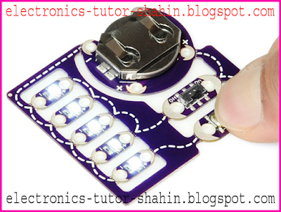
To add a little zest to your wearables you're looking for, it's bright, white LEDs do not get more delicious. But, if you're new to e-textiles game, really general electronics, cable (or sewing) can seem like a daunting task in a deliciously thought circuit. E-sewing kit ProtoSnap our more basic, yet useful, some of the concepts taught in the circuit is aimed at, so you confidently of anything you fancy LED, switches, buttons, and the battery can throw.


ProtoSnap - E-Sewing Kit Getting Started Guide

E-sewing kit looks like one of the keys to the whole board should arrive. Each component is already wired together, so if you toggle switch and / or push button to the right five LEDs can illuminate. If you look closely, you'll notice that the big board is a separate board is comprised of eight. This can be broken down into eight pieces each, serving as a separate board, however you see fit, so you can implement them in your project. Let's dig a little deeper into each part.

LilyPad Coin Cell Battery Holders
The energy that drives e-sewing kit. Just like your favorite toy, batteries, not included with the kit, so you can insert into a 20mm coin cell battery holder to do it. Are you just about anywhere you find "normal" AA or AA batteries to buy should be able to find this type of battery. Look for a CR2032 battery type.
When you get inserting the battery, it is inserted with the correct polarity. The positive side is usually a "+" is indicated, and it usually got it some other text. Batteries should be inserted, so that the positive side of the coin-cell touch the top of the container. Insert the batteries in backwards, do not fret if you can not do anything to break ... it just will not illuminate.
One last point here, if you really look closely Coin Cell LilyPad board, despite more than one character '+' s'll notice and "-" s printed board. The four petals of the lily pads on each label. Petal is a LilyPad where a connection should be made on whether you're sewing or welded place. Please note that the Board LilyPad E-sewing kit at least two petals of each individual and if they have specific functions - they're labeling (like + and). Just as we discussed in the next couple of boards to keep an eye on things.

LilyPad LED
ProtoSnap - E-Sewing Kit Getting
The E-sewing kit really make them shine! LED everywhere these days, it almost feels like electronics are required to have at least more than a blinky light. Therefore, there is no doubt that, should you want to add some other everyday items.
If you look closely at the LED board, I would like to draw your attention to a few things. Each LED on the board of two components, one little black resistance, and is driven in a large white-yellow. Obviously, the LED where the light comes out. The working behind the scenes to prevent a "current-limiter as"; Led his job to make sure it does not explode, and it will do its job well.
Just as the currency of the cell boards, each petal is with the "+" or one labeled "-". If you have a sewing line, board've noticed that seems to connect all together. The meandering line it is a representation of wire that's going on in the e-sewing kit, wired it up to show you how all of this stuff is just not there. Note that "-" "-" LEDs are connected to each petal petals coin cell board? This is for you, electronics ... It's really just one big game of connect the dots. Not so bad, right? But the pluses of LED plus battery does not seem to be connected to? They are the first of our next two boards like they're making a stop-over look.

LilyPad slide switch and button board
ProtoSnap - E-Sewing Kit Getting Started Guide
One of the basic rules of electronic circuit ... unless it's a circuit that will not work. There is a closed loop current is flowing. We use the open and closed circuit switches to manipulate, bending our will power!
Their "off" state, each switch to act as an open circuit (ie not closed). You can tell from the sewing line, battery switches and LEDs, "+" is added in each of the petals; They are a happy, close circuit to prevent the forming of forming both components.

However, if you are "on" switch slide, or buttons actuate, the switch is in a closed circuit. Imagine wire extending through the switch now, "+" battery "" LED is connected to, and in some glorious kit, making white light should be!
ProtoSnap - E-Sewing Kit Getting Started Guide
At this point you are probably aware of the effectiveness of a variety of e-sewing kit are switched on. Button, a "momentary switch" which means it is a closed circuit tripping-ness, it is only run when the button is actuated. Slide the switch state is relatively stable, until the other side of the slide switch is on or off.

Once you have gotten your e-stitch kit comes with the job, learn how to break it down and learn how to stitch your next project in Part 2 of this tutorial test.

Boxing Timer

Boxing and Making Noise:
If you want a boxing match, you know that two people 'box' round each other. For training, boxers, boxing, so their bodies during a bout 1 minute to 3 minutes, and the rest can be used as a war on the base at the same time, use a timer.


Our native format in front of me, the timer re-creation of the Academy. At the gym, and a common boxing timer is used to keep the bulbs burn out. The LED lasting at least 30 times longer than regular incandescent bulbs is unacceptable in this day in age. This is common in timer also expensive ($ 99) is!

Boxing Timer
Boxing Timer
Some days it is painful an engineer. Looking at this hunk of metal, I know that there is a microcontroller inside, a loud speaker, a couple of switches, some lights, and a whole lot of empty space. ..
This is a pretty straight forward project! Forgive me, but I tend to use a lot of things around the office that are available. And since this project was meant to be an example, I will use all the elements of the hole.

I hope you can use in your own projects in this part of the project:
  • Boxing Timer Eagle file
  • Boxing Timer Firmware
  • STK500 / Arduino serial bootloader
  • Boxing Timer Schematic
Boxing Timer
Boxing Timer
As you might guess, but I, ATmega168 (for the last year or so, my favorite) is based on the Arduino LilyPad 8MHz internal oscillator, along with serial boot-loader. what is this? Serial Arduino bootloader loader is based on the STK500. This is me, but instead of using a hardware programmer will be able to ATmega168 reprogram over a serial link. This code development cycle is a little easier, and users Arduino board can be used with their environment.

So there Micro, 5V supply, the painfully bright LED, and there are three rocker switches. A rocker switch (on / off) is used for other switch round length (2 or 3 minutes) and the rest of the time (1 minute or 30 seconds) is used to control.

Programming the timer using the FTDI Basic breakout.
I tried to increase the volume of the speaker এলএম 386 1W audio amplifier used. It's loud and annoying, but enough for a gym environment is not very loud. My supply voltage is only 9V (12-15V would be better), and I believe the speaker is a bit small for my application.

LED requires a maximum of 80 mA of power, so I used a basic N PN 2N3904 transistor circuits. I 20mA LED normal use, I would have driven directly from AVR - but this LED is bright.

Boxing at the gym, these are hardly the timer is turned off, so I chose to use LED instead of incandescent bulbs. Green, yellow, and red indicates where the round timer. Large 10mm LED, 80mA LED is. I covered LED development, they burned my peripheral vision so badly! For actual use, I try to disperse some of the LED light cracked the top of a Dremel tool. It helped, but LED is still very strong.

Boxers in different bags and 3 minutes, 1 minute off, their bodies get used to exerting power for a certain length of training for the equipment. When the yellow LED goes off
3 minutes 30 seconds of round (warning at the end of the round) left. The three lights, a loud tone, along with boxer at what point they have to learn in a given round.

The Box
The Box
Enclosures difficult to change! Luckily, there are tutorials we refer to Casey. Using a Dremel tools made all the difference. SparkFun pretty soft plastic enclosures make it easier to drill / cut / submitted to the beat. It's obvious that I need more practice, but in the box. I have three spots cut out switch, and the buzzer sounds coming from the increase in the number of holes drilled.

And there you have it - a boxing timer. This is an excellent example of a microcontroller can be used for the project. In this case, the microcontroller reads a couple of switches, which makes noise, different LED control, and his life is just "delay_ms" counting the cost of the majority.

I hope you can use in your own projects in this part of the project:
  • Boxing Timer Eagle file
  • Boxing Timer Firmware
  • STK500 / Arduino serial bootloader
  • Boxing Timer Schematic
Cheers!
Nathan Seidle