Thank you for buying a SparkFun Flex Sensor! This unique material sense, it is much lower. It opens up a wide range of projects including:
- Whiskers on robots
- Gloves know what your fingers are doing
- You can say that the door remains open how far they
- You know that if you're shaking their hands stuffed animals
... And other uses limited only by your imagination.
How it works
Sensors embedded in one side of the conductive particles in a polymer ink it is printed with that. When the sensors are simple, about 30k Ohms of resistance to ink particles. When the sensor is bent away from the ink, conductive particles, increasing resistance to this move further away (50k Ohms of the sensor, 90º is bent as the diagram below). When the sensor is out again, straightens, resistance to the original value. By measuring the resistance, you can determine how many sensors are being bent.

How to use it
Note: While the sensor (black squares in the area) of the active part of the strong, the sensor is able to pin-ended kinking and eventual failure. We restored or protected areas (for example, clamping or pin down the earliest black square sensor gluing) in this area to ensure that the sensor can not flex along with the rest of the recommendations.
The easiest way to incorporate this sensor into a voltage divider in your project using it. The need to prevent this circuit. 10K 100K from the standard will work, but here we are in a 10K resistor (SparkFun part number of the COM-08374, also Radio Shack, etc. Our inventor of Islam and locally) will use. Your microcontroller using the flex sensor circuit connect to the following:
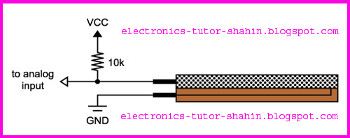
And a voltage divider resistor flex sensors, which are determined by a ratio of two to prevent the formation of VCC separated. When the sensor is simple, 10K and 30K resistor voltage VCC flex sensor output will be around 75 percent. When the sensor is low, about 83 percent will increase the voltage VCC (voltage divider for mathematics tutorial). You can use 5V for VCC, then you will see when the sensor is straight about 3.75V, and 4.17V by about 90º when the sensor is low. The numbers will be different for different sensors; For the most accurate results, you have to test specific sensors and use those numbers to your code.
Here is a basic Arduino sketch to show you the output from the sensor:
    // Flex sensor test program
// Mike Grusin, SFE, 2011
// This program is free, use it however you wish!

// HARDWARE:
// Make the following connections between the Arduino and the flex sensor
// Note that the flex sensor pins are interchangeable

// Sensor pin - GND
// Sensor pin - Analog In 0, with 10K resistor to +5V

// INSTRUCTIONS:
// Upload this sketch to your Arduino, then activate the Serial Monitor
// (set the Serial Monitor to 9600 baud)

void setup()
{
  // initialize serial communications
  Serial.begin(9600);
}

void loop()
{
  int sensor, degrees;

  // read the voltage from the voltage divider (sensor plus resistor)
  sensor = analogRead(0);

  // convert the voltage reading to inches
  // the first two numbers are the sensor values for straight (768) and bent (853)
  // the second two numbers are the degree readings we'll map that to (0 to 90 degrees)
  degrees = map(sensor, 768, 853, 0, 90);
  // note that the above numbers are ideal, your sensor's values will vary
  // to improve the accuracy, run the program, note your sensor's analog values
  // when it's straight and bent, and insert those values into the above function.

  // print out the result
  Serial.print("analog input: ");
  Serial.print(sensor,DEC);
  Serial.print("   degrees: ");
  Serial.println(degrees,DEC);

  // pause before taking the next reading
  delay(100);
}
Counsel
- When it is bent away from the side of the conductive ink (with the text): The sensor only works in one direction. You can see a short response to the other side of the bow, but the "right" direction is not as nearly as much. (You need to measure the bending on both sides, then consider using two sensors, back-to-back).
- Manufacturing tolerances of the individual sensors will result in some variability. For the most accurate results, at different positions, and measure the value of your code that you can calibrate the sensor you are using.
- These sensors work best (and longest lasting) if they are bent over a large radius, kinked not. Keep in mind that the active area of the black squares.
- As noted above, the sensor is able to pin-ended kinking and eventual failure. We are reinforcing or protected areas along the rest of the sensor so that it does not flex recommend.
Have fun!
Enjoy your new sensor! If you have any other questions the UK (or show Eur-Distribution Project)% two, please do not hesitate to contact us so
No comments:
Post a Comment